
What is amplitude modulation?
Amplitude modulation (AM) is one of the simplest and oldest techniques used to transmit signals via radio waves. The principle consists of varying the amplitude of a sinusoidal carrier wave according to the information signal (audio, data, etc.) to be transmitted.
It was widely used in early radio transmissions (long, medium and short waves) and is still used in some specific applications, such as amateur radio and analogue broadcasting.
Basic principle
A sinusoidal carrier with a fixed frequency fc is used, which is modulated with an information signal m(t), usually analogue (such as voice).
The mathematical expression of an amplitude-modulated signal is written as:

with :
- S(t): the transmitted AM signal
- m(t): the information signal (base band) or modulating signal
- fc: the carrier frequency
- E: the base amplitude of the carrier
- ka: the amplitude modulation coefficient (often denoted μ (‘mu’))
and where
- E cos(2πfc) represents the sinusoidal carrier. In the absence of a modulating signal m(t), the transmitted signal S(t) will therefore be equal to the carrier
- The term 1+kam(t) represents the envelope of the modulated signal. It acts directly on the amplitude of the carrier. To ensure that this amplitude always remains positive and non-zero, it must be ensured that:

which is the same as:

If this is not the case, overmodulation occurs, causing:
- Unnecessary frequency content: overmodulation generates additional unwanted spectral components
- Envelope distortion: the AM signal loses its shape in proportion to m(t)
- Zero-axis crossing: the envelope can become negative, which disrupts demodulation
- Envelope detector failure: a simple rectifier will follow the absolute envelope of the signal, but this is no longer faithful to the original information
To avoid distortion, it is important to ensure that
Frequency representation
If kam(t) is a pure sinusoidal signal with frequency fm, i.e. kam(t) = mcos(Ωt), the spectrum can be easily calculated:
S(t) = E (1 + mcos(Ωt)) cos(ωt) ; where ωt=2πfc
= E cos(ωt) + Emcos(Ωt)cos(ωt)
= ![]()
The frequency analysis of S(t) shows three components:
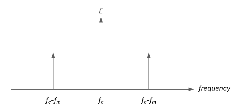
- The carrier at frequency fc
- A lower sideband at fc– fm
- An upper sideband at fc+ fm
If the modulating signal is sinusoidal (spectrum limited to 1 line), this line is found on either side of the carrier in the spectrum of the modulated signal.
This result can be generalised to any modulating signal s(t):
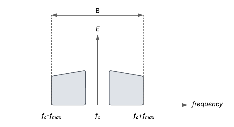
- the shape of the spectrum of m(t) is richer than a simple line
- the highest frequency contained in the modulating signal is called fmax. For a modulating signal that is sinusoidal, as in the example above, fmax = fm
- the spectrum of m(t) is found on either side of the carrier in the spectrum of the modulated signal
Amplitude modulation (double band with carrier or DSB-AM) therefore uses a bandwidth of B=2fmax, which is twice that of the original signal.
Derived modulation types
There are several variants of classic AM:
| Variant | Description | Advantages |
|---|---|---|
| DSB-AM | Double sideband with carrier | Easy to detect but not very efficient |
| DSB-SC | Double sideband without carrier (Suppressed Carrier) | More efficient but more complex demodulation |
| SSB | Single sideband | Spectral optimisation; used in HF |
| VSB | Vestigial sideband | Compromise used in analogue TV |
Advantages and limitations
✅ Advantages :
- Ease of implementation (simple oscillators and detectors)
- Easy demodulation with a simple envelope detector
- Upward compatibility with traditional receivers
⚠️ Disadvantages :
- Low spectral efficiency
- High sensitivity to noise and interference
- Energy waste in carrier transmission
Production of an AM signal and transmitted power
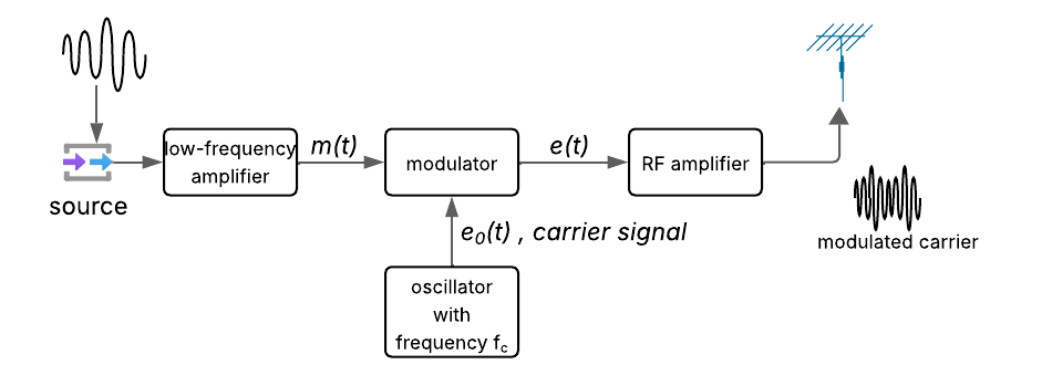
To transmit a signal using AM, the carrier is modulated by the low-frequency information signal using a modulator.
An AM signal can be generated using a multiplier as follows: – The modulating signal m(t) is offset by a DC component A – The resulting signal A + m(t) is fed into one input of the multiplier – The carrier signal e0(t) is applied to the other input
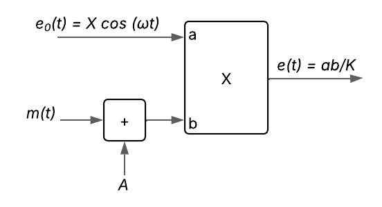
Let’s denote K as the gain of the multiplier. The AM signal can then be expressed as: ![]()
This shows that the modulation index M — defined as the ratio of the maximum amplitude of the modulating signal to the DC offset — is given by ![]()
Therefore, by adjusting the value of the DC component A, one can control the modulation index and ensure the modulation stays within the desired range.
Transmitted power
The AM signal modulated by a sinusoidal signal ![]() (see the paragraph ‘frequency representation’) is applied to the antenna, which behaves like a resistive load R with respect to the output amplifier.
(see the paragraph ‘frequency representation’) is applied to the antenna, which behaves like a resistive load R with respect to the output amplifier.
The total power dissipated in the antenna is then: ![]()
💡 Note: In conventional AM transmission, a significant amount of power is allocated to the carrier, which is continuously transmitted—even when no signal is being modulated. However, since all the useful information resides in the sidebands, it is possible to reduce power consumption by suppressing the carrier and transmitting only one of the sidebands. This technique is known as SSB (Single Sideband) modulation and is widely adopted in portable and long-distance communication systems for its spectral efficiency and energy savings.
Demodulating an AM signal: extracting useful information
The demodulation of an AM signal consists of recovering the original signal m(t) from the modulated signal S(t). This is an essential step in restoring the transmitted information, whether it is an audio signal, a data stream or telemetry.
The simplest method is to use envelope detection: The AM signal is rectified (by a diode) and then filtered using an RC circuit. This removes the high-frequency components and retains only the envelope, i.e. the low-frequency signal m(t).
This method is very accessible: it does not require any synchronisation with the carrier. However, it does have its limitations, particularly in the presence of noise or overmodulation. Let’s take a closer look at the two main techniques used.
Envelope detection (peak detector)
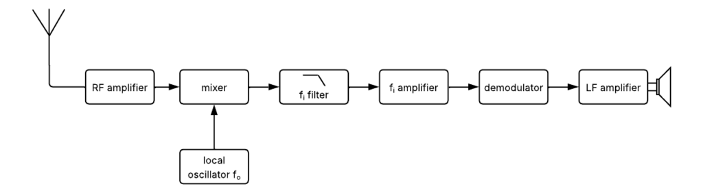
In a conventional superheterodyne AM receiver, the signal is first transposed to an intermediate frequency fi via a local oscillator + mixer, then selectively filtered.
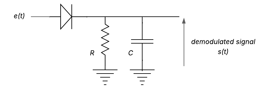
Once this step has been completed, demodulation can be performed via a peak detector, consisting of :
- a rectifier diode,
- an RC low-pass filter.
The time constant τ of the RC circuit must be large compared to the carrier period (τ≫1/fc ) and small compared to the modulation signal variation period (τ≪1/fm).
Indicative formula for dimensioning
![]() where Fmax represents the maximum frequency of the modulating signal, i.e. the useful bandwidth of the signal to be recovered after demodulation.
where Fmax represents the maximum frequency of the modulating signal, i.e. the useful bandwidth of the signal to be recovered after demodulation.
Note:
- The diode must have a low threshold: germanium peak diodes (~0.2 V) are ideal.
- If the signal is too weak, the diode does not conduct sufficiently → loss of signal.
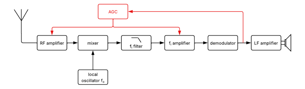
- In the event of overmodulation, the envelope becomes unrepresentative of the message: severe distortion. To limit this problem, an automatic gain control (AGC) amplifier is usually inserted before demodulation. It dynamically adjusts the signal level at the detector input.
Synchronous detection
More accurate but more complex, synchronous detection involves multiplying the AM signal by a sinusoidal signal synchronised with the carrier. This detector reproduces a faithful version of the modulating signal, even in the presence of noise or low levels.
Mathematical principle

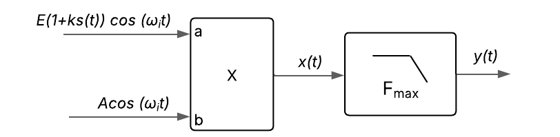
- The useful component is
 , obtained after filtering
 - The rest is eliminated by a low-pass filter
- Synchronous detection requires a local signal in phase with the carrier.
- This signal can be recreated from the AM signal by:
- clipping + selective filtering
- or phase-locked loop (PLL), used in modern integrated circuits
Even if the signal is heavily noisy, synchronous detection remains functional, whereas the peak detector becomes ineffective.
In practice, for amateur radio
AM transmissions have a ‘vintage’ flavour that is highly appreciated in certain parts of the HF band. Although less efficient than SSB, AM still allows DX contacts to be made in good conditions… provided you have a little space for a suitable antenna and well-adjusted modulation (avoid overmodulation!).
To sum up
Amplitude modulation is an essential foundation of radio telecommunications.
It paved the way for more modern technologies, while retaining its value for experimentation, education and certain forms of broadcasting.