Originally published by me in 2017 on the website of the BDX radio club, it was written based on the page written by ON3MEE. The original article was slightly adapted with the agreement of its author before being reproduced on the BDX website. We would like to thank him once again. Finally, it is reproduced here in English in order to share knowledge.
Introduction
There is a very special and exciting area of radio. The magic of this place captivates those who venture there. The doors to a world where the distant suddenly becomes close open. It guarantees and creates special bonds between a community, whose fate seems to separate them, and their homeland. Welcome to the world of shortwave!
Throughout this article, I will introduce you to the magic of shortwave (SW). We will start with a little physics and history, then briefly discuss the main users of SW. The topics covered will be broadcasting, amateur radio telecommunications, maritime and meteorological telecommunications, humanitarian aid and CB. The aim is to introduce you to a facet of radio that had its heyday and is now gradually being forgotten.
History and physics of waves
We need to start with a little physics and history to get a clear understanding of certain fundamental terms and concepts. I have tried to make this chapter as interesting as possible by focusing on the essentials. Despite this, it may still seem rather academic.
A bit of history
Before delving into a bit of academic theory, let’s start with an introductory chapter. We will discuss some of the developments in radio since its discovery up to the present day.
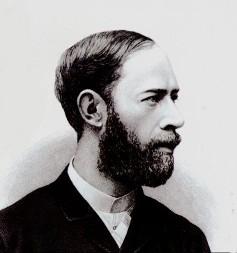
It all began in 1886 when Heinrich Rudolf Hertz demonstrated the existence of electromagnetic waves of a completely different nature. Using a spark gap, a device consisting of two balls at a certain distance apart that emitted waves through electric arcs, he created a type of radiation that was invisible and previously unknown. Other pioneers subsequently continued Hertz’s work. Initially, waves were detected using very rudimentary systems such as Branly’s coherer (an iron filings detector). Another well-known figure, Guglielmo Marconi, perfected the telegraph and invented the wireless telegraph in 1896. He began his work with Branly. In 1901, the year of the first Nobel Prizes, he succeeded in making the first transatlantic transmission from Poldhu to Newfoundland. He sent this telegram to his colleague Branly: ‘MR MARCONI SENDS MR BRANLY HIS RESPECTFUL COMPLIMENTS BY WIRELESS TELEGRAPH ACROSS THE CHANNEL, THIS BEAUTIFUL RESULT BEING PARTLY DUE TO THE REMARKABLE WORK OF MR BRANLY’.
The navy and military quickly understood the benefits. By 1901, several ships were equipped with wireless telegraphy. The distress code CQD was put into service. In 1906, De Forest invented the triode. This was a major step forward! It enabled audio amplification and radiotelephony.
However, a problem began to arise for TSF1: the first electric arc transmitters broadcast on all frequencies at the same time. It became very difficult to distinguish between stations. Tuning circuits and a frequency plan were then imposed.
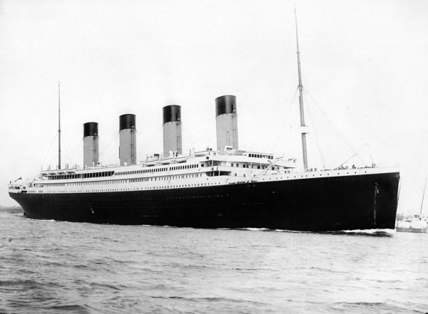
In 1912, a tragedy occurred that no one is likely to forget: the sinking of the Titanic. Morse code distress calls made it possible to rescue those who had managed to board the lifeboats. The new SOS code was used for the first time. Easier to recognise and quicker to type, it quickly replaced CQD.
During the same period, telephony developed rapidly. Experiments were conducted with transmitters to transmit voice. Crystal radios were quite widespread and did not require batteries to operate. With the advent of the Great War, progress only accelerated. A listening system was installed in the Eiffel Tower. The Germans transmitted their war orders in plain language, and France was able to communicate with Russia (before the Great Evening).
During the 1920s, radio broadcasting gradually began to take hold. At first, it was experimental. Music was broadcast at certain times, along with news bulletins. The first tube radios appeared in living rooms. The superheterodyne method was invented. Programmes were always broadcast live. Singers performed live. Soap operas were also broadcast. Aircraft were equipped with radios to communicate with airports and with each other.
At the same time, amateur radio operators began to take an interest in OC and experiment with it: with little power (QRP), they could communicate with the other side of the world. It was only then that people began to see its potential. Before that, everyone swore by LW and MW. Telephony was becoming increasingly important compared to wireless telegraphy.
The 1930s were marked by the democratisation of tube radios. They became widespread and found their place in every family. The quality of broadcasts improved and became more stable. The invention of magnetic tape made it possible to record reports and rebroadcast programmes. But live songs were still in vogue. Frequency modulation (FM) was developed on an experimental basis: it was useful for reducing interference. The first televisions also appeared during this decade. The first radar was used on board a ship to avoid icebergs.
Cryptography also experienced considerable growth. The Germans used Enigma to encrypt transmissions.
Then came the war. The five years of conflict accelerated progress even further. Smaller, portable devices had to be developed for use in the field (the famous backpack J ). New transmission codes appeared. Radar was perfected by the British to the point where it could detect a small object measuring just 30 cm in the sky.
In the field of portable devices, Motorola manufactured the first transportable transceiver at the end of the war. It was given the name walkie-talkie. The primary purpose was to stay in contact with headquarters. The device was smaller than backpack models. However, it was rarely used to coordinate missions between sentries from the same commando unit. This strategy, which is widely used today, could have further improved mission tactics. It was only too late that we realised the services they could have provided. The first walkie-talkies were only used to communicate with headquarters and not between two contingents. Today, communication via these portable devices is a strategic asset!
Début des années 50, le transistor est né. Ce nouveau composant va révolutionner le monde de l’électronique en général. Fini le temps des lampes à la fois fragile et volumineuses. On put miniaturiser les appareils de radio et les ordinateurs. Le transistor est un composant actif semi-conducteur au silicium (au début au germanium) qui a l’avantage d’être très petit et surtout de consommer beaucoup moins d’énergie que son homologue le tube (quelques dizaines de mW contre quelques W par composant). De plus les tensions mises en jeux sont bien plus réduite : 5 ou 12 V contre 90 ou 300 V concernant les tubes. On pouvait désormais écouter les informations ou la musique partout et transporter son récepteur dans une simple poche. Cette invention fut surtout pratique à la miniaturisation des talkies walkies.
It was also during this period that frequency modulation emerged from the laboratory. The VHF I band from 88 to 100 MHz was allocated for high-fidelity radio broadcasting. The era of HF interference caused by impulse-type disturbances was almost over.
In telecommunications, digital modes replaced the famous Morse code. RTTY (radio teletype) was invented. These modes enable telexes to be transmitted via radio waves. They are very reliable and highly resistant to noise. In the 1960s and 1970s, all communications were mainly transmitted via RTTY and shortwave.
The advent of the first satellites led to a decline in shortwave transmissions: VHF, UHF and UHF frequency bands offer many more channels than SW, and the bandwidth can be wider. This allows for the transfer of much more data.
At the same time, radio amateurs who had previously used AM invented a new modulation technique: SSB. This was a huge technical advance. It offered enormous bandwidth savings and guaranteed signal robustness over longer distances. Today, it is the most common mode for HF telecommunications. It is used to modulate all kinds of digital modes and, of course, voice directly.
Nowadays, SW is increasingly being abandoned in favour of satellite and cable networks. However, the OC band is still popular with radio amateurs, the military and deep-sea navigation.
What is an electromagnetic wave?
In summary
What should we remember from this chapter on wave physics?
The link between frequency and wavelength
That the radio spectrum is divided into several frequency bands
That the propagation of electromagnetic radiation depends heavily on the environment and certain properties
The concept of order of magnitude: “adapting by thinking” to the wavelength
That the size of an antenna is of the same order of magnitude as the wavelength, i.e. ¼ wavelength for a dipole.
That long, medium and short waves are strongly reflected by the ionosphere.
Short waves propagate by successive reflections, which increases their range.
The propagation of OC changes depending on the time of day and the season, so the frequency will need to be changed during the day.
The SW band is between 3 and 30 MHz
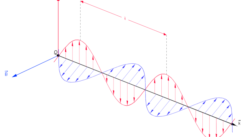
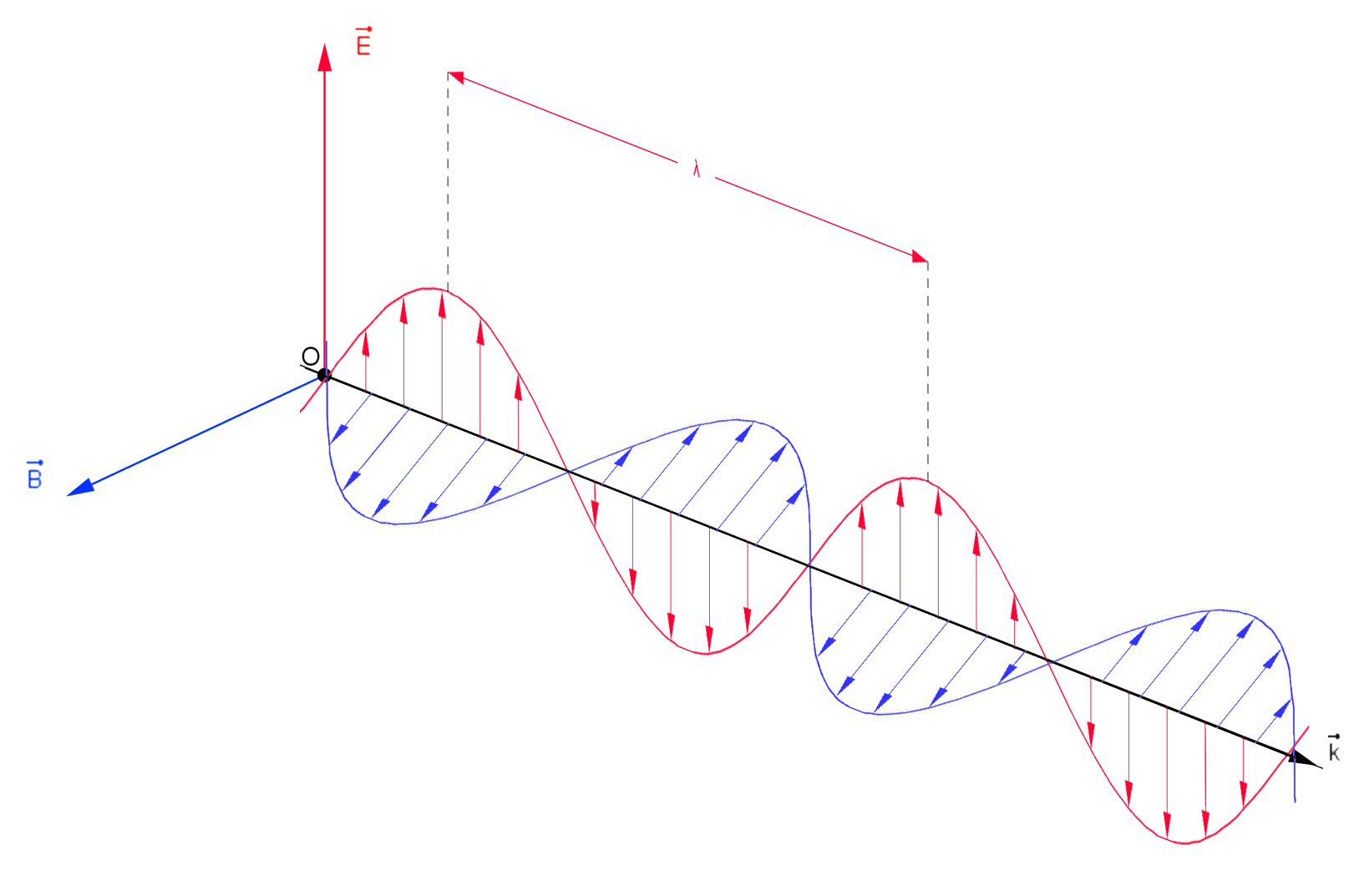
Light, X-rays, ultraviolet rays, infrared rays, gamma rays and radio waves are all part of the electromagnetic wave family. Electromagnetic radiation is characterised by its frequency f and wavelength λ. It propagates at a speed c of 300,000 km/s, in a straight line and in all directions. Just like an acoustic pulse that propagates from one point to another through variations in air pressure, electromagnetic waves propagate in the surrounding medium through variations in the electric field E. The fields are perpendicular to each other and vary sinusoidally and in phase.
The wavelengthλ (lambda) is defined as the distance between two successive peaks. In general, the wavelength is the distance that must be travelled from one point of the function f(t), at speed c, over one period of oscillation of the source, to the next point of the same amplitude. The unit of measurement is the metre (m).
The frequencyf is the number of waves per second. It is the number of oscillations of the emitted source per unit of time. Frequency is expressed in Hz (Hertz).
The periodT is the time it takes for the wave to travel the distance of one wavelength. More generally, it is the time it takes to emit one oscillation from the source. Unit: s (second).
Relationship between frequency and wavelength :
Where A is the amplitude, ω is the angular velocity in rad/s, T is the period, and φ is the phase shift angle.
Radiation is classified according to its wavelength on a line. This classification is called the electromagnetic spectrum.
This concept is easily understood with the help of the diagram opposite. It starts on the left with signals of very long wavelengths and ends on the right with those of very short wavelengths. From left to right,
Radio waves (ELF -> microwaves): those that interest us,
Infrared (IR): light radiation emitted by heat sources,
Light: visible spectrum
Ultraviolet (UV): responsible for sunburn and many processes in the atmosphere,
X-rays: radioactive radiation used for medical imaging,
Gamma rays: radioactive radiation produced during a nuclear reaction
We will focus on radio. The table below shows the radio spectrum:
Band
Frequency
Designation
LW – LF – GO
30 kHz – 300 kHz
Long waves
MW – MF – PO
300 kHz – 3 MHz
Medium waves
SW – HF – OC
3 MHz – 30 MHz
Short waves
VHF
30 MHz – 300 MHz
Very High Frequencies
UHF
300 MHz – 3 GHz
Ultra High Frequencies
SHF
3 GHz – 30 GHz
Super High Frequencies
EHF
0 GHz – 300 GHz
Extra high frequencies
Short waves (HF – SW – OC) are our focus in this article. It should be noted that the SW band ranges from 3 MHz to 30 MHz. Some consider that it already starts at 1600 Hz. In fact, these designations are purely conventional and do not change the properties of the radiation around the boundary between two bands.
Properties of radio waves and their impacts
Just like sound and light, radio waves have physical properties. I will briefly outline them.
Reflection: obstacles (mainly metals) act as mirrors for radio waves (radar principle).
Diffraction: a wave of a certain length bypasses an obstacle that is smaller than that wavelength
Refraction: when a radio wave passes from one medium to another, its angle is deflected
Absorption: certain media composed of certain molecules absorb radiation at a specific frequency (e.g. microwaves are strongly absorbed by water)
The first two properties vary depending on the wavelength (and therefore the frequency) in the following way: as the wavelength increases, the waves bypass large obstacles and reflect less effectively. This explains why certain bands are suitable for certain applications.
The order of magnitude of the wavelength is a very important concept to understand: with a 10 km wave, one must ‘think in terms of 10 km’, and for a 12 cm microwave, one must think in terms of 12 cm. The sizing of devices and applications are highly dependent on the first two properties, i.e. the wavelength. Furthermore, refraction and absorption must not be overlooked. At certain specific frequencies, they also play a role.
With regard to absorption, it is important to note that moisture absorbs microwaves to a great extent. The higher the frequency, the greater the absorption. Above 1000 MHz, this factor becomes significant. At 2.4 GHz, the resonance frequency of water molecules, it can be said that this factor is predominant for wave propagation. Losses caused to terrestrial microwave links can be enormous in humid weather. Compared to satellite links, a microwave link remains at low altitudes, where most of the humidity is found. However, it can be neglected below 1000 MHz. Between 1000 and 1500 MHz, it begins to become significant, and above that, it is an important factor to consider! The graph below clearly illustrates this phenomenon.
Here’s a good tip: compare radio waves to light! Radio waves have difficulty passing through obstacles and are governed by the same laws as optics. Only a few small details change (a sheet of paper or a window does not stop a microwave, a person’s hand will reflect it: NOTION OF ORDER OF MAGNITUDE)! The environment is therefore predetermined to ensure a good connection.
The antennas
To create a radio wave, a high-frequency alternating current must flow through a conductor: the antenna. The back-and-forth movement of electrons in the antenna creates an electric field and a magnetic field that varies at the frequency of the oscillating current. This is the main element that allows radiation to be received and transmitted through the air.
Antennas can be divided into omnidirectional and directional types. Omnidirectional antennas radiate in all directions and pick up signals from all directions. Wire antennas, telescopic antennas, dipole antennas, etc. are omnidirectional antennas. They generally have a unit gain. Directional antennas, on the other hand, radiate more specifically in one direction at a certain angle. When receiving signals, they favour reception from that direction compared to omnidirectional antennas. They have a gain greater than unity. Yagis, Quagis, etc. are directional antennas.
The power gain is expressed in dB (decibels). This unit is logarithmic. For a gain of *10, we will have +10 dB. We increment by 10 dB each time the gain is multiplied by 10. So, for a factor of *100, we will have +20 dB.
As already mentioned above, wavelength determines the size of devices: the size of an antenna depends on its wavelength. This rule cannot be ignored.
Why do we need ‘¼ wave’, ‘½ wave’, etc.?
An antenna must be tuned to the operating frequency for optimal performance. If it is out of tune, it will not pick up the desired signal well. During transmission, the greater the detuning, the greater the standing wave return: some of the energy is returned to the transmitter and is not dissipated in the air. Efficiency is very poor and there is a risk of burning out the radio. This standing wave return can be measured with an SWR meter. This device displays a ratio (called SWR: standing wave ratio) from 1 to infinity. The ideal SWR is 1 (impossible to achieve as it is a borderline case). Between 1 and 2, it will be considered correct and without damage to the transmitter. Between 2 and 3, it is better not to force transmission. Above 3, it is strongly recommended to stop transmission, even for a fraction of a second.
The antenna can be tuned using a coupler. This is an LC tuning circuit. Thanks to this, the transmitter believes it is connected to a well-tuned antenna. However, it is important to note that there is a loss of efficiency: the coupler dissipates excess energy in the form of heat. It therefore only allows part of the energy to reach the antenna. There is therefore a loss in the line.
The special properties of short waves
So far, we have looked at all the general principles of radio waves. But why focus on SW rather than MW and LW? Until now, I have only discussed propagation in an ideal homogeneous medium with a few obstacles. On Earth, there is another factor to consider: the ionosphere.
The ionosphere is an atmospheric layer located between 80 and 500 km above sea level with specific physical and chemical properties. This layer absorbs and reflects certain frequency ranges and is transparent to others. SW waves are reflected by it. LW and MW waves are ground waves. As for VHF, UHF, etc., they continue their journey through space. Reflected waves propagate beyond the visible horizon, while VHF and UHF waves cannot be received beyond the curvature of the Earth (100 km). ????
A small portion of LW (mostly ground waves) are reflected off the lower layer of the ionosphere (80 to 100 km). The range is 2,000 km. MW follow the same phenomenon, but they do not travel as far: 500 km.
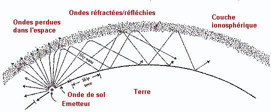
Short waves, on the other hand, are reflected both by the middle and upper layers (100 to 200 km) and by the Earth’s surface. As they bounce around, they travel around the globe. Their range can be greatly increased with minimal power (a few watts). It is easy to see why they are so valuable for telecommunications.
Three zones are determined around the transmitter: the near zone, the shadow zone, and the far zone.
Near zone: at a short distance from the transmitter, direct radiation is received. This zone extends slightly beyond the visible horizon: 50 to 100 km.
Shadow zone: beyond the horizon, nothing can be received. Radio waves pass over the receiver and are reflected by the ionosphere. It extends from 100 to 500-1000-2000 km (variable limit).
Far zone: the reflected rays reach the ground. The signal can be picked up again. The extent of this zone is highly variable: from 1000-2000 km to more.
Part of the radiation is reflected by the ground towards the sky.
A new bounce begins.
Propagation varies depending on the time of day and the season: it is influenced by the ionisation of gases in the ionosphere by the sun and solar winds. In general, this ionisation improves propagation, but it can also attenuate it. At a given time of day, one frequency band may be strongly received and another may be completely silent. At another time, the latter will be preferred over the former. In practice, in Europe, it is said that 80 m and 40 m ‘work well’ in the morning before 8:30 UTC and that 20 m is for late morning and mid-afternoon. In the evening, we tune in to 80 and 40 m. These observations represent the general case, but nature sometimes offers unusual and rare openings on other bands: 18 MHz, 28 MHz, etc. Low frequencies always propagate well, but higher frequencies are more timid. During solar cycles (every 11 years, solar activity becomes intense), cosmic particles from the sun increase ionisation. This has the effect of promoting exceptional propagation conditions on all radio bands.
VHF, UHF, SHF, and other waves undergo intense propagation phenomena due to the troposphere. For example, in the 144 MHz band (VHF RA band), it is possible to regularly establish contacts over distances of 400 km.

